To Build a Robot Part 5
April 11, 2010
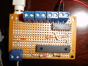
I found a 15+ year old pre-printed circuit board from Radio shack and found it to fit just right for what needed. It would be nice to have a properly designed circuit board printed out but this will do nicely for now. Later after I decide if this is the best way to arrange the different parts of the robot I will put something together in Eagle and have someone create a cheap board for this.
Here is the finished solder job ( a bit butchered but it works )
The battery and motor connections are done through some nice terminals I picked up for $2 for the 6 pack. The PWM wire connector from the Arduino is a chopped up extension cord selected because it has enough wires to run the 4 PWM lines and the power and ground wire. It is also nicely shielded to keep noise down.
I will be adding a second L293B H-Bridge to this but I haven’t finished the soldering yet. I also need to setup the output for the second motor from the first L293. I left the solder points for the TLC 5940 NT un soldered so later i can setup a series of them to run even more motors. I will likely add a simple connector for the additional boards once i get a bit closer. When complete this board will drive 4 motors with a total of 2 amps at 3V. Due to the gearing it is more than enough. The gear I am using in the video below is a Tamiya 70103 Universal Gearbox. At some point I may change out the H-Bridge for a heavy duty mosfet for something that can withstand 30A of current.
Here’s a video of the motor spinning backward and forward.
Motor Controller
Next up, completion of the soldering on this board and beginning to fabricate the legs.

