VDIP1 USB Host Controller
March 27, 2010
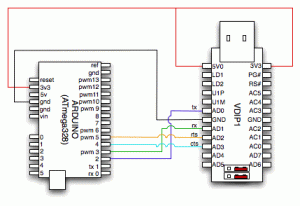
I got my VDIP1 USB Host controller from Saelig today and was able to get it hooked up and reading a Flash drive in a couple hours. Because the Arduino only has one TX / RX serial pin if you connect it using them you cannot communicate with the computer over the built in USB UART on the Arduino. To get around this limitation there are a number of libraries that allow serial communication over non-serial pins.
I chose the NewSoftSerial library to give access to the VDIP1. The first attempt was to use the AFSoftLibrary and it just did not work properly causing some strange looping of the Setup() method. After switching to the NewSoftSerial library everything started working and I had no trouble doing a DIR and creating a new file on the flash drive. I am posting an early version of the sketch just so i can get a good example and a picture / schematic out so expect updates later. Keep reading for the schema, pic and sketch.
Update: I changed the sketch and schematic / pic to include the RTS / CTS flow control.
Click here to see the picture and sketch.
Read the rest of this entry »
To Build a Robot part 3
March 26, 2010
Encouraged by my quick work with the H-Bridge I decided to add in the accelerometer. Below is the wiring diagram and sketch I am using. The sketch just spins the motor forward or backward based on the X tilt / accel.
To Build a Robot part 2
March 26, 2010
I was able to get the L298B working on the first run. The motor runs nicely on a couple double A batteries. I will be adding extra controllers and parts later but it was good to get it running without any issues.
Read the rest of this entry »
To Build a Robot Part 1
March 25, 2010
Doing a bit of research on what is needed I picked up a few parts that are needed for the project I want to do. I would like to put together a bipedal robot that balances. I have some strange ideas on what will make a good design but the basics come first. Today I stopped by San Diego Electronics Supply for some parts.
It’s a bit scrubby but the people working there are super nice and very knowledgeable.
I got:
- 4x 4066’s to for the RX / TX on the serial.
- TCL5920 to make more PWM pins available
- 2x 2N3904 Switching Transistor to act as the switch for the 4066’s
- 2x L293B H-Bridge chips to control the motor current from the 5920.
- 1x 4051 to give me more sensor pins for rotation sensors
I will try out the L293’s tonight with one of my DC motors.
MUD on an Arduino
March 19, 2010
While waiting for my parts for my robot I started a little project with my Arduino. The original idea was to make a little irc bot based on the code at http://vimeo.com/1622823
The initial project started out as a simple led on / off just like what was shown. The code was simple for the Python script and the Arduino code was very simple. I wanted to make a more interactive experience so the idea of doing a mini-mud came to me.
USB UART Replacement
March 19, 2010
Shortly after getting my Arduino i was playing with some DC motors and was powering the device through the USB->serial cable. It turns out this wasn’t the best idea and after a couple hours i was doing something and attached a motor mistakenly without a resistor when I should have had one. The result was burning ozone and a super hot FTDI chip.
I was going to get a new Arduino when I came across this blog post:
http://www.neufeld.newton.ks.us/electronics/?p=328
I ordered a new chip from sparkfun for only $3.95 (shipping was just as much).
Rather than waiting for the new one to come I decided in a fit of activity that the old one should be removed. With a bit of prying and desoldering it was removed. During the extraction two of the wires in the board itself got pulled up.
After a week or so the new chip arrived in the mail. I started to prep the area and fix the pulled up wires and found my old radio shack soldering iron just not up to the task. After a trip to Frys I had in hand some 60/40 solder, Rosin Flux and a new Elenco SL-540 soldering iron.
After getting the new gear it was a much easier task. I dropped a gob of flux on the pulled up wires and pushed them in to place. I dripped some solder blobs on the contacts in the corner and attached the chip. After that i just wicked away the excess using a braided wire and used a tiny bit of solder and lots of flux to get the rest of the contacts down.
Here’s the finished result:
I was terrified of plugging it in but it turns out it worked perfectly, it just looks horrible.


